


Concrete Overlays
Design of Concrete Overlays for Ashpalt Parking Lots
Overlays | Installation Process | Design Factors | Success Story | Ultra-Thin Overlays
Recommendations and procedures for designing concrete overlays to rehabilitate deteriorated asphalt parking lots are presented here for design professionals.
PAGE OUTLINE
1. Evaluation of Existing Parking Lot Pavement
1.1 Traffic Loads
1.2 Drainage
1.3 Inadequate Pavement Section
1.4 Subgrade
1.5 Poor Construction
1.6 Existing Parking Lot Geometry
2. Design of the Concrete Overlay
2.1 Traffic
2.2 Strength of the Existing Pavement
2.3 Selection of the Overlay Thickness
2.4 Special Considerations for Badly Failed Areas
2.5 Correcting Drainage and Grade Problems
2.6 Areas Needing Thickened-Edge Slabs
2.7 Joint Layout
2.8 Concrete Quality
4. References
Concrete overlay is a major rehabilitation technique for providing an old pavement with a strong, long-life, low-maintenance pavement structure. The procedures described were developed through 30 years of experience and research in overlaying airport runways, heavy-duty highway pavements, and light-duty roads and streets.
Parking areas for commercial, industrial, public, and residential buildings are an important part of the overall facility. Attractive parking areas add to the commercial appeal of shopping centers. They contribute to employee morale and productivity at industrial facilities. Safe, light-reflecting parking areas attract renters and buyers to residential projects. All too often inadequate construction, improper maintenance, or total neglect will cause parking area pavements to fail. A deteriorated parking lot full of potholes or ponded with water will turn customers or potential renters away. Deteriorated pavements are a safety hazard to everyone using the parking lot.
Evaluation of Existing Parking Lot Pavement
To ensure satisfactory performance of a new concrete overlay, the factors that caused deterioration of the existing asphalt parking lot need to be corrected or recognized in the design. The engineer should investigate the existing pavement to find the probable reasons for its deterioration. Asphalt pavement failures can generally be attributed to one or more of these factors: drainage problems, traffic, subgrade condition, inadequate pavement section, poor construction, inadequate mixtures, or substandard materials.
Traffic Loads
Parking lot designs are generally based on traffic load and frequency assumptions made before the facility is put into service. Heavier vehicles or greater traffic volumes than anticipated can contribute to early pavement deterioration. Before designing the concrete overlay, the engineer should find out the types of vehicles currently using the parking lot and any significant changes in vehicle weight or traffic volumes anticipated at the facility. Many localized pavement failures can be attributed to heavy truck or bus traffic concentrated at loading or unloading zones and pickup areas. These areas should be identified and provided with more load-carrying capacity in the overlay design.
Drainage
Another frequent cause of parking lot pavement deterioration and failure is improper or inadequate drainage. Most subgrade soils are weakened when they become saturated with water. Water left standing in a parking lot, for whatever reason, eventually finds its way into the subgrade. Traffic over this weakened area causes the asphalt pavement surface to crack. This in turn allows more water to penetrate into the subgrade and accelerates the deterioration. The engineer should evaluate the existing drainage conditions and ensure that the reconstructed parking lot is sloped properly to provide adequate drainage. For concrete pavement, a minimum slope of 1% or ⅛ in. per foot toward the drainage intake is recommended. Catch basins and other storm drainage structures should be checked for adequate capacity. If they are inadequate to handle the design rainfall, they should be improved before reconstruction of the parking lot begins.
Inadequate Pavement Section
All too often, parking lot pavements are an afterthought in the original design and construction plans. Little attention is given to designing pavement sections that will carry anticipated traffic on the subgrade soils at the site. The owner may specify a pavement thickness that is inadequate in order to reduce initial construction costs. The result is a pavement section that is insufficient for the traffic and subgrade conditions. Ultimately, the lot will deteriorate and fail.
To design an economical concrete overlay, the original asphalt pavement thickness must be determined. During the pre-design site investigation, several test holes should be excavated to ascertain the thicknesses of the asphalt surface and base course, and the materials used in the surface, base, and subgrade.
Subgrade
The support given to the concrete overlay by the subgrade under the existing asphalt pavement is an important factor in deciding the thickness of the overlay. The engineer should determine the strength or engineering classification of the subgrade soil at the site. If the existing parking lot is generally in fair condition but has localized areas of severe deterioration due to wet or soft spots, it may be more economical to repair these areas so that the concrete overlay is not designed for e worst condition.
Poor Construction
Deterioration of asphalt pavement caused by poor construction, such as bleeding, ruts, thermal and age cracking, shoving, and raveling, should not affect the performance of the concrete overlay. Surface irregularities will, however, increase the amount of concrete needed to repave the lot. This should be considered when estimating material quantities needed in the rehabilitation
Existing Parking Lot Geometry
Premature pavement failure is often caused by heavy trucks and buses using areas of the parking lot that were designed only for passenger cars and light truck traffic. If site inspections reveal that heavy traffic has contributed to failure in automobile parking areas, the engineer should consider design alternatives, such as traffic channelization and exclusive truck areas, to keep heavy trucks off the thin pavement sections. If this cannot be done, the pavement structure for the entire lot should be designed to carry the truck traffic anticipated.
Design of the Concrete Overlay
Once the existing site conditions have been analyzed and the factors that contributed to the failure of the existing pavement determined, the design of the parking lot overlay can begin. As with any pavement design, the thickness of the new concrete surface is determined by the type and volume of traffic expected, the strength of the existing pavement, and the material properties of the concrete to be used.
Traffic
An estimate of the type and volume of traffic using the lot is an essential step in thickness design. For critical parking lots, traffic surveys or market studies for businesses served by the lot can be used to determine initial traffic and predicted traffic growth. In most cases, however, these detailed predictions are not necessary. Recommended overlay thicknesses shown in Table 1 are based on typical parking area traffic categories described in Table 2. Using this simplified procedure, the designer needs to know only the approximate type of traffic expected to use the lot. For example, if heavy truck traffic is excluded from automobile areas, these areas can be designed using the car parking area traffic category A, Table 2.
|
|||||||||||||||||||||||||||
|
||||||||||||||||||||||||||||||||||||||||||||||||||||||
Strength of the Existing Pavement
To determine the overlay thickness, the support modulus of the subgrade (k) and existing pavement (km) must be estimated. The designer can learn subgrade soil type or support values from plans and soil borings taken during the original construction, if available, or as part of the site investigation. Figure 1 may be used to correlate the modulus of subgrade reactions (k) to various soil classifications, including American Association of State Highway and Transportation Officials (AASHTO) and American Society for Testing and Materials (ASTM)-Unified-soil classification systems. Figure 1 also contains the California bearing ratio (CBR) and other correlations to k value. Knowing the soil classification or CBR, the designer can estimate the k value of the subgrade. Such an estimate is adequate for design use with the traffic categories shown in this publication. For special parking lots carrying abnormally heavy truck weights and volumes, the support conditions need to be more thoroughly evaluated; design methods given in Reference 2 should therefore be used.
The existing asphalt pavement, even though it may be badly deteriorated, does provide support for the concrete overlay. Table 3 gives approximate support modulus values (km) for the various total thicknesses of the existing asphalt surface and granular base.
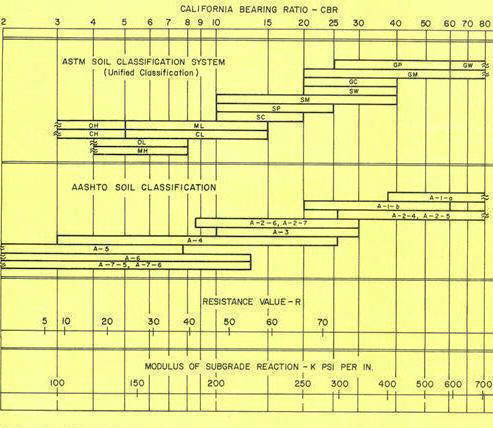
Fig. 1. Approximate interrelationships of soil classifications and bearing values.
|
||||||||||||||||||||||||||||||||||||||
Selection of the Overlay Thickness
Once the traffic category and support modulus (km) have been established, conventional concrete pavement design procedures are used to determine the required thickness of the overlay. Table 1 recommends thicknesses based on the design procedures of the Portland Cement Association. These are the
minimum thicknesses that should be used on the project. Gradelines should be set at the site to maintain these minimum thicknesses regardless of the irregularities of the existing pavement surface. The option to mill off asphalt surface in some areas depends on the desired final grade and the grade and irregularities of the existing surface.
Special Considerations for Badly Failed Areas
Areas of the parking lot that exhibit excessive deterioration and serious failure should be singled out for special treatment. If the failure is attributed to heavy truck traffic (around trash and garbage pickup containers, for example), the overlay in those areas should be specifically designed for the heavier traffic. Potholes should be filled with an aggregate base material and thoroughly compacted with mechanical compaction equipment. Alternatively, flowable fill may be poured in holes and depressions to insure adequate support without compaction. Large areas that exhibit severe subgrade failure should be excavated and the unsuitable material replaced. Aggregate base course material should be compacted. A thin layer of sand may be needed to prevent intrusion of the subgrade material into the base course. The existing pavement grade should be matched before the overlay is placed.
Correcting Drainage and Grade Problems
During the design process the engineer should check the original drainage design to ensure that catch basins and storm drainage structures are adequate to carry the anticipated stormwater. Grade for the overlay should be set to provide a minimum of ⅛ in. per foot of fall toward the drainage structure. Drain inlets and manholes must be raised to match the elevation of the new pavement.
In some cases it may not be possible to raise the elevations of existing curbs or building entrances. In these situations, existing pavement abutting the structure should be removed in a tapered section out to the location of the first joint in the concrete overlay. Underlying materials in the section should be adequately compacted. At vehicle entrances, the thick end of the tapered section should be excavated to allow for an additional 20% to 25% thickness of concrete. The increased thickness compensates for the support lost by removal of the original pavement material.
Areas Needing Thickened-Edge Slabs
Extra concrete thickness is needed at slab edges where isolation (expansion) joints have no load transfer provisions (keyways, dowels, or aggregate interlock) and at exits and entrances at the parking lot perimeter. A tapered edge providing 20% to 25% additional thickness compensates for the lack of joint load transfer to adjacent slabs. The taper should extend 3 or 4 ft back from the slab edge.
Joint Layout
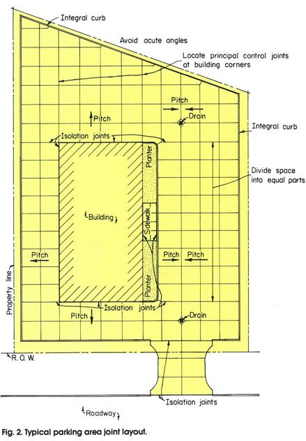
Joints in concrete parking areas aid construction and minimize uncontrolled cracking. They can also delineate parking areas and traffic lanes. Designing a joint layout requires good judgment based upon a few basic rules. Figure 2 shows a typical parking area that employs the following guidelines:
● Unless local experience indicates otherwise, joint spacing in feet should not exceed 30 times the slab thickness (that is, 10 by 10 ft for a 4-in. slab thickness). Regardless of slab thickness, joint spacing should not exceed 15 ft for unreinforced pavements. (Longer joint spacings can be used in reinforced pavements; see Reference 3 for the design of joints for reinforced pavements.)
● Joints should be laid out to form approximately square panels. When this is not practical, rectangular panels can be used if the long dimension is no more than 1½ times the short.
● All transverse and longitudinal joints should be sawed, grooved, or formed to a depth of at least one-fourth the slab thickness (that is, 1 in. for a 4-in. slab).
● Isolation (expansion) joints should extend full depth and should be abutting or
within the pavement area.
● Joints should run continuously through the paved area and extend through the integral curb. Joints can be terminated and offset at isolation joints.
● Where there are manholes, catch basins, small foundations, and other built-in structures, joints should be laid out so that they meet the corners of the structure.
● Control joints should be offset at least 1½ ft to avoid acute angles or small
sections of slabs at curbs.
● Control joints should be sawed as soon as possible without raveling the new
concrete.
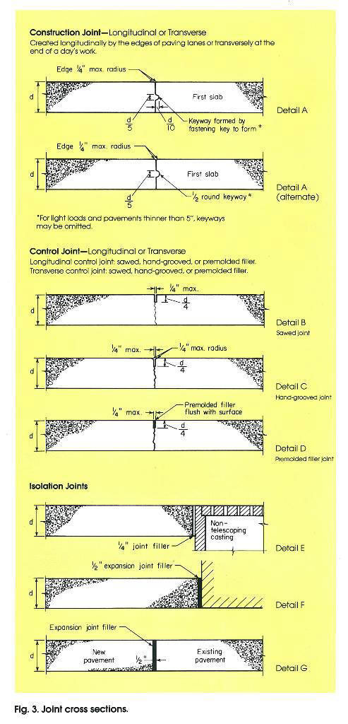
● Construction joint locations should be determined by the contractor's equipment and procedures. Construction joints should be placed between adjacent slabs that have different thicknesses (for example, a 4-in. automobile parking area abutting a 6-in. truck lane). Details of joint cross sections are shown in Figure 3 below.
For unreinforced pavements, with their short joint spacings, dowels are not needed at transverse joints unless there will be more than 200 trucks per day per lane. For reinforced pavements, with longer joint spacings, the joints should be doweled. Dowels are sized as follows: diameter, ⅛ in. per inch of slab thickness; length, approximately twice slab thickness. Additional details on joint layout and design can be found in References 3 through 5.
Concrete Quality
Durability of concrete depends on quality of aggregates used, level of air entrainment, strength and water-cement ratio, and placing and curing practices used by the contractor. Details of the requirements for quality concrete are given in Reference 6.
Ready mixed concrete for parking lots is normally specified in accordance with the requirements of ASTM C-94. The specifier designates:
● Size of coarse aggregate (for paving, generally ¾ in., 1 in., or 1½ in.
maximum, but not greater than ¼ the slab depth).
● Slump (for paving, 4 in. maximum).
● Air content (minimum of 6% in severe climates where freezing and thawing
conditions are predominant and deicing salts are used; 3% average in milder
climates).
Compressive strength is specified and tested on parking lot paving projects. A minimum compressive strength of 3500 psi is recommended; this should be increased to 4000 psi in areas where freeze-thaw durability is a concern.
Construction Procedures
There are many acceptable procedures for paving parking areas. Equipment ranging from simple hand screeds and floats to slipform paving machines can place, compact, and finish concrete paving economically and efficiently. The contractor should choose construction methods based on the project size and the availability of equipment. Once the type of equipment has been selected, the paving sequence and jointing plan should be developed to assure a smooth construction operation. On small jobs, the concrete placement sequence is not critical, but on larger projects it may be more efficient and convenient to place concrete in alternate lanes.
Regardless of the methods selected to place the concrete overlay, the contractor should:
● Ensure that the pavement is sloped a minimum of 1% or ⅛ in. per foot toward the drainage structure.
● Make sure that the existing pavement surface is free of debris and loose materials. It is usually not necessary to moisten the existing asphalt mat; when temperatures are extremely high, however, moistening can keep the materials cool through evaporation. In no case should concrete be placed over water ponded on existing asphalt surfaces.
● Avoid over-finishing the slabs. Generally a bullfloat finish is adequate. Skid- resistant texture can be added with a burlap drag, broom, or Astroturf drag.
● Cure the fresh concrete pavement. Liquid-membrane curing compound is usually recommended as the most cost-effective curing agent.
Unless special concrete mixes are used, automobile traffic should be kept off the parking slab for three days, and truck traffic for about seven days.
References
1. Urban Transportation Planning for Goods and Services, Federal Highway Administration, 1979.
2. Thickness Design for Concrete Highway and Street Pavements, EB109P, Portland Cement Association, 1984.
3. Joint Design for Concrete Highway and Street Pavements, IS059P, Portland Cement Association, 1975.
4. Whitetopping an Asphalt Parking Area, PA152B, Portland Cement Association, 1984.
5. Building Quality Concrete Parking Areas, PA147B, Portland Cement Association, 1981.
6. Design and Control of Concrete Mixtures, EB001 T, Portland Cement Association, 1979.